

Home > Products > Communication Equipment > Repeater > 1800MHz&2100MHz&2600MHz Tri Band Bandwidth Adjustable Digital Signal Booster

1800MHz&2100MHz&2600MHz Tri Band Bandwidth Adjustable Digital Signal Booster
Specifications of 1800MHz&2100MHz&2600MHz Tri Band Bandwidth Adjustable Digital RepeaterModel: BT-VS37E6 The Digital Repeater is designed to provide a more cost-effective solution than adding a new Base Transceiver Station (BTS) to improve signal coverage and communication quality in single ......
Send Inquiry
Product Description
Specifications of 1800MHz&2100MHz&2600MHz Tri Band Bandwidth Adjustable Digital Repeater
Model: BT-VS37E6
The Digital Repeater is designed to provide a more cost-effective solution than adding a new Base Transceiver Station (BTS) to improve signal coverage and communication quality in single system. And its easy installation and maintenance can help carrier get fast return.Model: BT-VS37E6
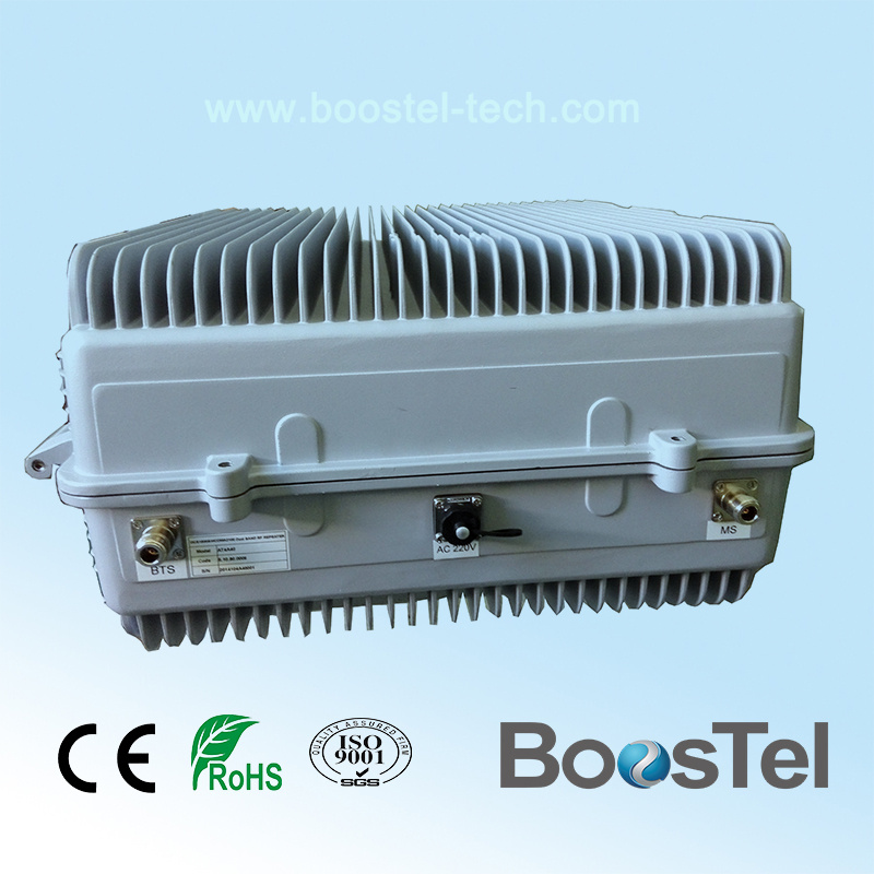
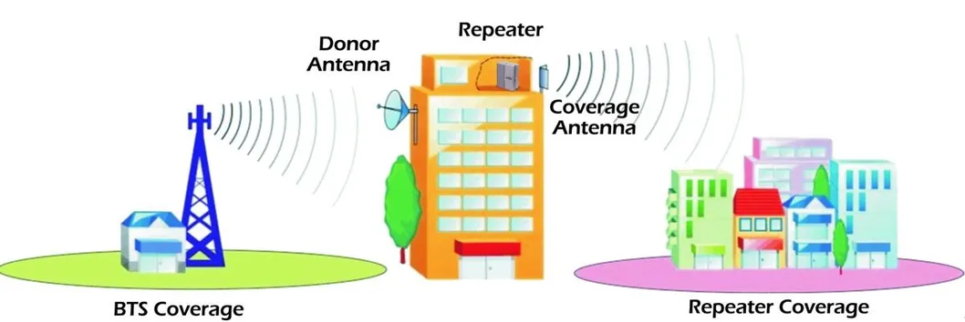
The repeater is working as a relay between the BTS and mobiles. It receives the low-power signal from BTS via the Donor Antenna, linearly amplifies the signal and then retransmits it via the Coverage Antenna to the weak/blind coverage area. And the mobile signal is also amplified and retransmitted to the BTS via the opposite direction.
Features |
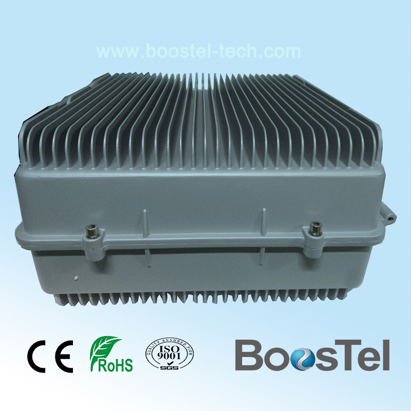
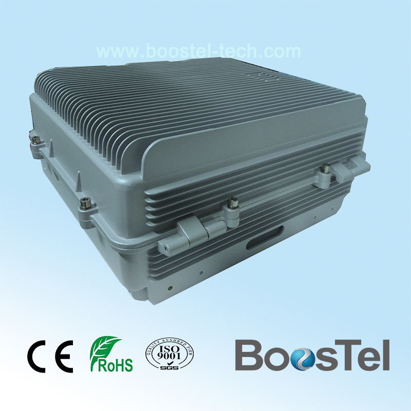
- Aluminum-alloy casing with IP65 protection has high resistance to dust, water and corroding
- Software defined filter supporting adjustable in each individual frequency band
- Low interference to BTS by adopting linear amplifier with high gain and low noise
- Adopting filter with highly selectivity and low insertion loss eliminates interference between uplink and downlink
- USB port provides a link to a notebook for local supervision or to the built-in wireless modem to communicate with the NMS (Network Management System) that can remotely supervise repeater's working status and download operational parameters to the repeater
Applications |
| Outdoor: | Airports, tourism regions, golf courses, tunnels, factories, mining districts, villages, … |
| Indoor: | Hotels, exhibition centers, basements, shopping malls, offices, parking lots, … |
Applications
Application Diagram |
Technical Specifications
| Items | Specifications | |||
| System | GSM/UMTS/LTE | UMTS/LTE | LTE | |
| Working Frequency (Customized) | Uplink | 1710~1785MHz | 1920~1980MHz | 2500~2570MHz |
| Downlink | 1805~1880MHz | 2110~2170MHz | 2620~2690MHz | |
| Bandwidth | 2 sub-bands, each 0.2~25MHz Tune Bandwidth | 2 sub-bands, each 0.2~25MHz Tune Bandwidth | 2 sub-bands, each 0.2~25MHz Tune Bandwidth | |
| Maximum Gain | 85±3dB | |||
| Maximum Output Power | Uplink | 30dBm | ||
| Downlink | 37dBm | |||
| ALC | Support | |||
| Gain Adjustment Range | 0-31dB in step of 1dB | |||
| Voltage Standing Wave Ratio | ≤ 1.5 | |||
| Maximum Input power(Non-destructive) | 0dBm | |||
| Error Vector Magnitude | ≤ 8% | |||
| Peak Code Doman Error | ≤ -35dB | |||
| Spurious Emission | 9KHz~1GHz ≤ -30dBm | |||
| 1GHz~12.75GHz ≤ -36dBm | ||||
| Third-order Inter-modulation | Comply with 3GPP TS 25.106 V6.0.0 | |||
| Noise Figure | ≤ 8dB | |||
| System Delay | ≤ 8.0μSec | |||
| I/O Impedance | 50Ω | |||
| RF Connector | N-Type (Female) | |||
| Temperature Range | Operation: -25°C ~ + 55°C | |||
| Relative Humidity Range | ≤ 95% (non condensing) | |||
| Power Supply | AC220V,50/60Hz | |||
| Dimensions | 500*440*235mm | |||
| Weight | ≤45kg | |||
| NMS Monitoring Function(Optional) | Real-time alarm for door status, temperature, power supply, VSWR, etc; Remote control such as turn on/off, increasing/decreasing output power, etc; Real-time status for output/input power, UL/DL gain, all status of repeater etc. | |||
Installation & Commissioning 
Figure 1 Repeater Mounting Bracket
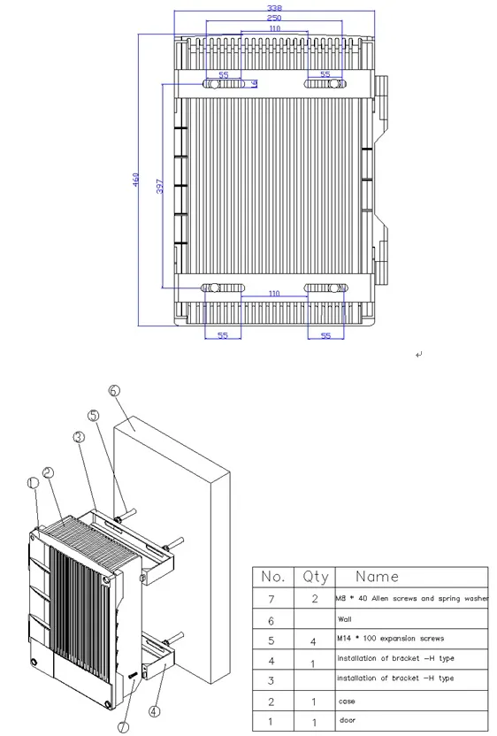
Figure 2 Repeater Mounting Bracket
1.1 Installation
1.1.1 Steps for mounting on the Pole
- At Donor site, install the FSR Donor Unit, Donor Antenna, Link Antenna, and RF cable as per specified plan and site layout. FSR Donor Unit can be pole-mounted using the brackets as shown below.
- Place M8 screws through the holes of H type brackets as shown in figure 1
- Fix combiner onto the H type brackets with M6 screws
- Fix H type brackets with combiner installed onto the pole with U type brackets and M8 screws
Figure 1 Repeater Mounting Bracket
- Orient the Link Antenna of Donor Site to the direction of the Remote Site.
- Use Site Master to measure the VSWR of the RF cable from the Link Antenna. The value should be less than 1.5; Otherwise, check the connectors and the installation of the cable.
- Start Commissioning the Donor Unit .
- Proceed to the Remote Site.
- At Remote site, install the FSR Remote Unit, Link Antenna, Coverage Antenna, and RF cables. Remote Unit can be wall mounted or pole mounted depending on the approved plan.
- Orient the Remote Link Antenna to the direction of the Donor Site.
- Using Spectrum Analyzer, check the Link RSL; adjust the Link Antennas of both Donor and Remote until the required RSL is achieved. Link RSL can be computed using conventional path calculation method.
- Then, measure the VSWR of the RF cables connecting with the Link Antenna of Remote Unit. The value should be less than 1.5, otherwise, check the connectors and the installation of the cable.
- Start Commissioning the Remote Unit .
1.1.2 Steps for mounting on the wall
- At Donor site, install the FSR Donor Unit, Donor Antenna, Link Antenna, and RF cable as per specified plan and site layout. FSR Donor Unit can be wall-mounted using the brackets as shown below.
- Make four marks on the wall according to the dimension shown as figure 2
- Drill four holes at position marked
- Fix two pcs H type brackets on the wall with M8 expansion screws
- Fix combiner onto the brackets with M6 screws
Figure 2 Repeater Mounting Bracket
6. The following steps are the same with step 4 to 12 for mounting on the Pole.

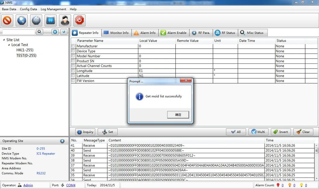
Figure3 Interface of NMS Board
1.2 Commissioning
- Connect the RF cable from Donor Antenna to the spectrum analyzer and check if the Donor Antenna is receiving the correct frequency; and then measure the signal level of the said frequency (RSL). Adjust the antenna to make the readings approach the recorded value on the survey report. Record all readings.
- Inside the repeater, disconnect the uplink duplexer to the ICS module so as to cut any signal coming from air going to the uplink duplexer and thus protecting the amplifier from damaging. Connect a 30 dB attenuator to the output of the repeater; this attenuator will serve as a load for the repeater. The purpose of this attenuator is to protect the equipments from damaging.
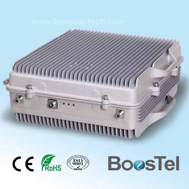
- Turn ON the repeater. Observe the LED display on the NMS board. Check for any alarm. Under normal condition, the POWER LED should be always green and the RUN LED should be blinking, the ALARM LED should be not bright with red color.
Figure3 Interface of NMS Board
Connect your laptop to the repeater via the data cable.
Related Category
Broadcast Intercom System
Communication Cables
Fiber Optic Equipment
Fixed Wireless Terminals
Other Telecommunications Products
PBX
Repeater
Telecom Parts
Telecommunication Tower
VoIP Products
WiFi Finder
Wireless Networking Equipment
Send Inquiry
Please Feel free to give your inquiry in the form below. We will reply you in 24 hours.